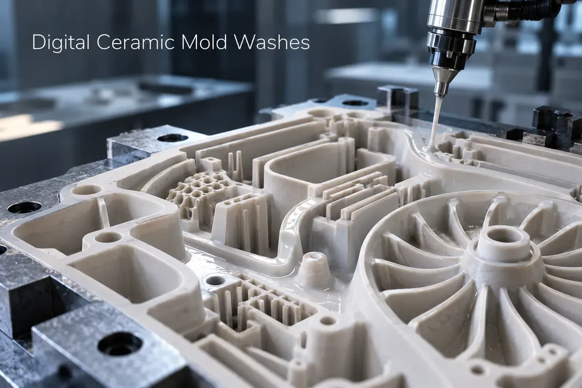
Digital Ceramic Mold Washes: Preventing Feature Bridging and Uneven Coat Pickup
Diagnose bridging and uneven pickup in digital ceramic mold washes. Separate local geometry, drainage, pore penetration and dry-film evidence before trials.
Process troubleshooting guide · Material focus: cristobalite-containing refractory wash development · Application: digitally manufactured ceramic molds · Audience: coating formulators, mold developers and quality teams
“Wash” means an applied refractory coating here—not a liquid for cleaning uncured printing resin. Substrate and thermal compatibility require separate approval.
Read the mold from its smallest recess outward. Is the opening still clear? Is the corner rounded? Has a curtain of coating joined two features that should remain separate? A smooth external face cannot answer those questions.
Digital manufacturing can reproduce a detailed geometry, but the applied wash becomes another geometric operation. Its local thickness, drainage and interaction with the substrate can change the usable shape. The practical target is not maximum coat pickup. It is adequate, repeatable coverage without obscuring the features the mold was made to reproduce.
This guide treats a cristobalite-containing powder as one candidate ingredient in a complete refractory wash. It does not assume that the powder alone controls coating behavior or that one formulation suits every printed ceramic, binder-jetted body or casting alloy.
Begin with a feature map, not a viscosity target
Choose the features whose function is most vulnerable to coating: a narrow slot, blind pocket, sharp internal radius, thin rib, vent or small opening. Photograph and measure them before coating. Confirm that depowdering, cleaning and any approved post-treatment have already left them open; a pre-existing obstruction is not wash bridging.
Define “bridging” operationally as a continuous coating span across an intended opening or separation. Distinguish it from a thick but attached corner deposit, a loose agglomerate and dried residue carried from another surface. These defects can look similar in a final photograph but demand different investigations.
Set local acceptance criteria from the mold drawing and process requirements. A useful criterion names the feature, inspection method and allowed condition after drying or firing. Do not invent a universal minimum gap or a fixed particle-to-feature ratio without validation.
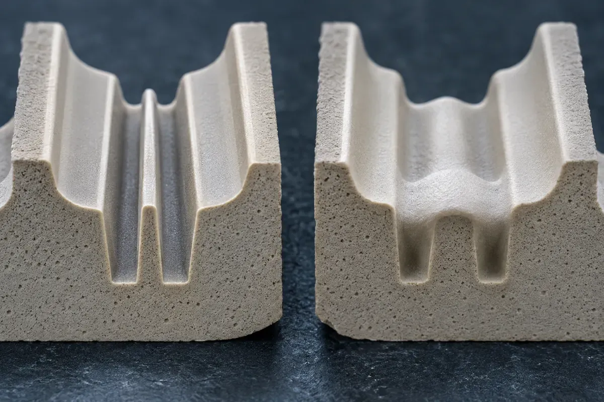
Follow the coating through three distinct events
1. Pickup during application
Record the application route: dipping, flow coating, spraying or brushing. Keep its relevant variables explicit rather than labeling all four “coating.” A dip trial needs its immersion, withdrawal and subsequent orientation recorded. A spray trial needs its delivery and overlap conditions. Comparing unlike routes does not isolate a powder effect.
On porous substrates, retained material may occupy both the surface and the pore network. Research on ceramic dip coating describes contributions from liquid entrainment and slip-casting behavior; its results also show that substrate porosity and application variables matter. That study used specific unfired ceramic tapes, so its numerical results are not a recipe for a digital mold. [1]
2. Redistribution before setting or drying
Observe where coating moves after application. Record persistent spans, drainage from pockets and accumulation on lower edges. Rotate only according to an approved trial plan: orientation is a variable, not an informal correction that changes from coupon to coupon. Use repeatable observation times to distinguish immediate pickup from later pooling.
3. The final dry deposit
Inspect again after the validated drying process. A satisfactory wet appearance does not establish the final opening, adhesion or deposit distribution. If the mold is subsequently fired, repeat the relevant dimensional and integrity checks after firing. Do not prescribe a drying or firing temperature without the substrate and binder requirements.
Use the defect to choose the next check
| Observation | Check first | Controlled follow-up | Avoid assuming |
|---|---|---|---|
| A span closes a narrow opening | Was it open before coating? Does the span form wet or dry? | Fixed feature coupon; compare application and drainage orientation | Smaller D50 alone will solve it |
| Heavy deposit in a pocket | Drainage path, local pooling and application history | Map local deposit after a consistent drain interval | The entire bath is too viscous |
| Mass pickup varies between coupons | Substrate state, bath sampling and weighing timing | Matched coupons; dry-mass and section evidence | Mass gain equals surface-film thickness |
| Deposit changes during the shift | Settling, evaporation, temperature and agitation record | Sample at defined locations and times | The incoming powder lot must have changed |
| Dry cracking or detachment | Local build, substrate compatibility and drying history | Compare sections and approved drying conditions | More binder is always the remedy |
Measure pickup without confusing it with thickness
For matched coupons, a useful tracking value is dry mass gain divided by a documented coated area. Define the initial and final conditioning states and verify that the substrate itself has not changed mass through moisture loss, dissolution or other treatment. Use an appropriate uncoated reference where the investigation requires it.
This value supports process comparison; it is not automatically an average surface thickness. Material can enter pores or collect preferentially in recesses, and the dry deposit has its own structure. A Foseco patent's experiments explicitly measured absorbed material, penetration depth and surface-layer thickness separately. Those sand-core results support the distinction between measurements, not a transferable thickness target for ceramic molds. [2]
Combine mass tracking with selected cross-sections or a suitable local measurement method. Mark the top, bottom, pocket and critical opening on each coupon. Report the method's limitations on rough or inaccessible surfaces rather than treating one external-face reading as the whole mold.
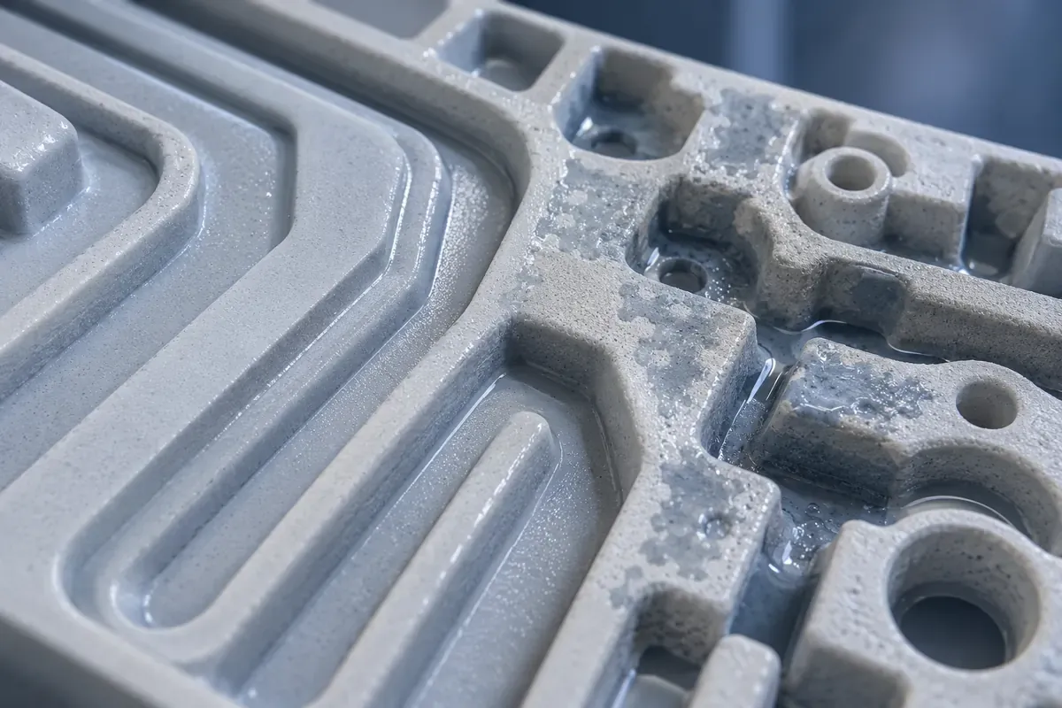
Control the bath, then investigate the powder
Record solids on a defined basis, temperature, mixing, rest time and sampling position. A single flow-cup value cannot describe every stage from application through rest. If viscosity measurements are used, retain the instrument, geometry, shear conditions and timing. Ask the formulator whether recovery after application needs characterization.
BYK's foundry guidance discusses viscosity reduction through dispersing additives separately from suspension stabilization through rheology additives. That separation is useful: lowering a measured viscosity and improving storage stability are not identical formulation tasks. It is not a recommendation to add a named additive without compatibility trials. [3]
For a candidate cristobalite grade, review the distribution beyond D50, method-defined oversize and dispersion evidence. Check whether the complete wash contains agglomerates or foreign debris. Any straining step must be compatible with the approved formulation; removing a fraction without assessment changes the material being tested.
Keep phase identity separate from coatability. XRD can distinguish crystalline phases, including polymorphs with the same chemical composition; a high SiO₂ result is not a phase-fraction certificate. Neither chemistry nor phase identification alone predicts bridging, drainage or adhesion. [4]
If defects appear only late in a shift, preserve samples of both the bath and uncoated substrates at the relevant times. Compare a retained reference wash on the later substrate and the later wash on a matched reference substrate, where practical. This crossover check can help separate a changing bath from a changing substrate condition. It does not identify the mechanism by itself, but it makes the next experiment more informative than replacing powder and adjusting dilution simultaneously.
Qualify detail retention before the casting trial
Use a repeatable coupon incorporating representative slots, pockets and orientations, made by the same route and post-treatment as the mold. Compare the reference wash with a limited candidate change. Hold the substrate, application and drying conditions constant until the first comparison is interpretable.
Require both local feature acceptance and repeatable coverage. Then assess adhesion, handling, thermal compatibility and any required permeability or casting behavior using the applicable process. Specialist coatings are offered for additive-manufactured sand molds, but their published application context does not validate a wash on a different ceramic substrate. [5]
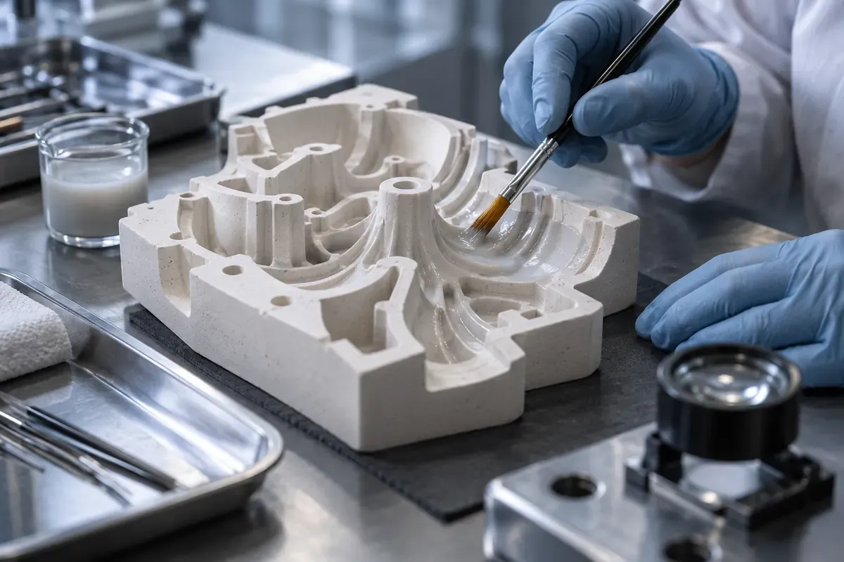
When reviewing controlled-phase cristobalite for digital ceramic mold-wash development, request the grade's actual phase evidence, chemistry, PSD method and batch documents. The product is a candidate mineral ingredient, not evidence of a qualified complete coating.
Our separate guide to cristobalite, ceramic-shell strength and knockout concerns a different performance question; shell results cannot replace deposition checks here. Share the substrate, smallest critical features, carrier, binder, application method and thermal route to define a relevant powder trial.
Request a Cristobalite Wash Quote
Frequently asked questions
Will finer cristobalite prevent bridging?
Not necessarily. Check agglomerates, complete-wash behavior, substrate interaction and drainage. D50 alone does not define the deposited geometry.
Can more pickup compensate for a rough printed surface?
Only if the resulting local coverage and critical features remain acceptable. Extra retained mass can also accumulate where it is unwanted.
Can sand-core coating data set our ceramic-mold limits?
No. Use those sources for measurement concepts; establish limits on the actual substrate and complete coating system.